The Nerve Impulse Seen from Outside
Dexter M. Easton July 2000 ©
Next topic Previous topic Table of Contents
Topic 14: Stimulating and recording arrangements
In the traditional depiction of the compound action potential, typically illustrated in textbooks, the sciatic nerve, suspended in air or submerged in oil, is slung onto two pairs of wires. An electric pulse delivered by the pair at one end stimulates the nerve, and the evoked compound action potential is recorded via the pair at the other end.
Here we take a different tack. The nerve remains immersed in physiological solution. When it is then drawn by suction into a tube, a thin film of the physiological salt solution remains between the nerve and the inside of the tube. During impulse propagation, the voltage drop due to longitudinal currents can be recorded along this layer of high electrical resistance, corresponding to Re in Fig. 2.
Figure 14. The nerve chamber (from Easton 1993, Adv. Physiol. Educ.).
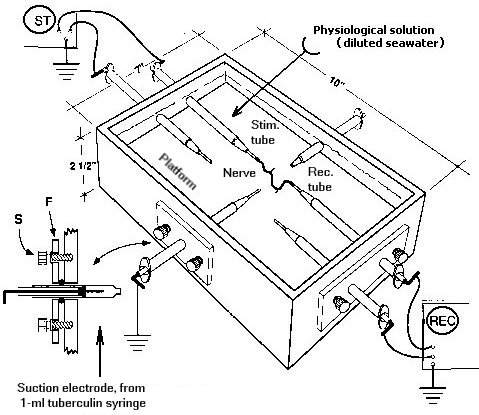
In a more convenient version of the original suction electrode design (Easton 1962), the device is fabricated from a 1-ml tuberculin syringe and mounted in a simple, custom built, nerve chamber (Easton 1991): A small hole is punched in the plunger terminal of a plastic tuberculin syringe. The terminal is cemented to the end of a short section of plastic tube, and a relatively nonpolarizable electrode of chloridized Ag wire is inserted. Each suction electrode is held in place by an O-ring at each end of the nerve chamber.
The branches of the proximal end of the nerve are drawn together, by suction, into the stimulating tube, and the distal end into the slightly smaller recording tube. Each tube is of such size that the nerve slides easily into it. In general, the looser the fit, the smaller will be the voltage drop. Why?
Next topic Previous topic Table of Contents