Topic 1. Electric currents flow in nerve
Between the inside and the outside of a nerve cell, you can record a voltage difference, as you might from a flashlight battery ("dry cell"), but less than 0.1 instead of 1.5 volts (<100 mV rather than 1500 mV). The inside would correspond to the negative pole and the outside to the positive. Thus the cell membrane is the location of an electromotive force. Electrophysiologists routinely measure the changes in this electric potential in single resting and active nerve cells. Electric currents flow longitudinally in the internal and external compartments as well as radially through the membrane, between the inside and the outside of the cell.
The flow of current outside a nerve is the main concern in this program.
The flow of current is easy to measure, and it is an important topic for practitioners of electroencephalography (EEG), electromyography (EMG), and electrocardiography (EKG).
The nerve membrane can be represented as an electric circuit. The pathways for current through and along the nerve membrane can be represented by symbols for electrical components such as a battery, with electromotive force EM, resistance, R, and capacitance, C. R is a measure of the opposition encountered to the movement of charges (the current) through a pathway, and C is a measure of the extent to which charge can be stored at a place along the path. Current (+ charges) tends to move toward a region of less positivity. A + pulse or signal appears as an upward (+) deflection of the cathode ray oscilloscope beam. Ohm’s law applies: the voltage difference between two points is proportional to the current, i.e., V = I×R, where the proportionality constant, R, is the resistance of the pathway. In the diagrams, arrows show the direction of current flow.
Figure 1. Diagrams of simple electrical circuits.
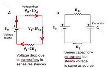
In the simple electrical circuit represented in Fig. 1A, positive current I flows through the series of resistors in the direction of the arrows. Recall Ohm’s law: V = I×R. The voltage drop along a path through which current flows easily is said to be of low resistance. A path of higher resistance provides a greater impediment to the current. In resistors arranged in series, as in the figure, the voltage drop (difference) across one resistor is the same proportion of the total V drop as the resistance R is of the total resistance of the series.
The total voltage drop is:
![]()
The IR drop, Ve, through Re, is only a fraction of the total:
![]()
Where VT = EM. Thus
![]()
If EM = 0.1 V, and Rs = 5000, Re and RI each = 50,000 ohms, what is the size of the voltage recorded in Re? What fraction is Ve of EM?
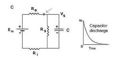
When (Fig. 1B) a capacitor is substituted for one of the resistors in Fig 1A, there is no voltage drop across any of the resistors because no current flows. Across the capacitor, there is a steady voltage difference, the same as across the battery, for the charge on the capacitor is the same as that on the battery in this instance. When the capacitor is placed in parallel with one of the resistors as in Fig. 1C, the voltage drop across the capacitor is the same as that across that resistor. If the circuit is then suddenly broken (at X (arrow), for example), current no longer flows from the battery. Instead, a pathway (a "short circuit") remains for the + charges on one side of the capacitor to move as current to the other side, thus eliminating the separation of charge and the potential difference. The time course of this discharge (an exponential decay) depends on the sizes of the resistor and of the capacitor.